| Device Areas |
Basic |
Reinforced |
Suppliementary |
Funional |
| Primary winding to primary winding |
|
|
|
x |
| Primary winding to grounded screen |
x |
|
|
|
| Primary winding to insulated body |
x |
|
|
|
| Primary winding to double-insulated body |
|
x |
|
|
| Primary winding to hazardous secondary |
x |
|
|
|
| Primary winding to ELV or grounded SELV |
x |
|
|
|
| Primary winding to ungrounded SELV |
|
x |
|
|
| Grounded screen to insulated body |
|
|
|
x |
| Grounded screen to double-insulated body |
|
|
|
x |
| Grounded screen to hazardous secondary |
x |
|
|
|
| Grounded screen to ELV or SELV |
|
|
|
x |
| Double insulation to double-insulated body |
|
|
|
x |
| Double insulation to hazardous secondary |
|
x |
|
|
| Double insulation to ELV |
|
|
x |
|
| Double insulation to SELV |
|
|
|
x |
| Hazardous secondary to ELV |
x |
|
|
|
| Hazardous secondary to grounded SELV |
x |
|
|
|
| Hazardous secondary to ungrounded SELV |
|
x |
|
|
| ELV to grounded SELV |
|
|
|
x |
| Grounded SELV to ungrounded SELV |
|
|
|
x |
| TNV to primary |
|
x |
|
|
| TNV to grounded or ungrounded SELV |
x |
|
|
|
| TNV to ELV |
|
|
x |
|
| TNV to grounded hazardous secondary |
|
x |
|
|
| TNV to ungrounded hazardous secondary |
|
x |
x |
|
|
Table I. Types of insulation required between device areas: B = basic, R = reinforced, S = supplementary, and F = functional.
|
The Concepts in Application
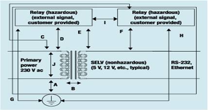
To determine the required creepage distance and clearance spacings for an electronic product, the best method is to first draw a block diagram of the design (see Figure 2) from which a table of the required spacings can be prepared (see Table II). For example, the primary section of a power supply is treated as a block. Spacings are examined between hot and neutral to ground and between all primary and secondary parts. Each circuit should be regarded as a block.
|
|
Figure 2. A block diagram of the electronic device for which the spacing requirements in Table II have been calculated.
|
It is important to note that the voltages of each block are not added together if they are powered from the same source (i.e., across a transformer). In the case of a relay contact where the contacts are connected to a different source, the two voltages are added together to determine the working voltage.
| Location in System |
Insulation Type |
Maximum Working Voltage(Vac) |
Required Creepage Distance |
Required Clearance (mm) |
Test Voltage
(Vac) |
| mm |
CTI Value |
| A |
Basic |
230 |
2.5 |
175 |
2.0 |
1500 |
| B |
Double |
260 |
6.4 |
175 |
4.0 |
3000 |
| C |
Basic |
460* |
6.3 |
175 |
3.2 |
1674 |
| D |
Basic |
460* |
6.3 |
175 |
3.2 |
1674 |
| E |
Double |
260 |
6.4 |
175 |
4.0 |
3000 |
| F |
Double |
260 |
6.4 |
175 |
4.0 |
3000 |
| G |
Basic |
230 |
2.5 |
175 |
2.0 |
1500 |
| H |
Basic |
230 |
2.5 |
175 |
2.0 |
1500 |
| I |
Basic |
460* |
6.3 |
175 |
3.2 |
1674 |
| J |
Functional |
230 |
2.5 |
175 |
1.5 |
1500 |
|
*Working voltage based on the rating of the relay contact plus 230V.
|
|
Table II. Tabulation of creepage and clearance distances required for the system diagrammed in Figure 2, which is characterized by Pollution Degree 2 and Overvoltage Category II. Insulation types are basic (B), double (D), and functional (F). Source: Tables 2L and 2H of IEC 60950.
|
Motien Technology’s most standard DC/DC converters are designed to have Functional Insulation, unless with other specified notes. For requirements of insulation and isolation, please check with us in advance.
|
|
 Case temperature and safe operation Case temperature and safe operation
We can see all the time in the specifications two different items: operating temperature and maximum case temperature, so which one defines the real performance of this device?
- Operating temperature range defines the temperature range which the converter can operate normally, and maximum case temperature defines the allowable maximum temperature by the case of the converter.
- When the device is working over the maximum case temperature, despite the environment temperature is still within the range of operating temperature, the forced heat sinking (air convection or other effective approaches) is absolutely required. The case temperature comes from environmental temperature and internal temperature rise. Over high case temperature damages the internal parts of converter and reduce the lifetime.
- Derating: When choosing converters, it’s a must to take into account the actual needs of the operating temperature range. Different temperature level use different materials and processes, so prices vary greatly. There are two choosing method: One is based on the use of power and package, if the use of power are close to the actual rated power, then the nominal temperature range modules must strictly meet the actual needs with even a slight margin. Second, choose in accordance to the temperature range. If a smaller temperature range is chosen as a result of considering the cost, but the temperature approaches now and then the limits of the situation, what should we do? Derating operation. Choose higher power or greater package products, to lower the temperature rise. Thus can be alleviated this contradiction to some extent. Derating ratio of different grades vary with the power, generally is 3~10W/°C above 50W. In short, choice of wide temperature range, the power can be used more fully and smaller package, but higher prices; choice of temperature range or products, lower prices, larger power margin and package.
- Safe operation: General recommendations of the actual use of power is 30~80% rated power of the converter. Too less loads lead to waste, too high loads will produce too much heat and are relatively not so stable. A waste of resources to load too light, too heavy on the temperature rise, the negative reliability. Some Motien products with higher output power usually provide 120 to 150% bearing, but it is not recommended to work long hours under the over load conditions. After all, this is only a short-term protection measuring.
- Keeping a good space and convection for air-circulation is highly recommended.
|
|
Ripple & Noise and Input filter…
- Ripple & Noise - Every single Motien product had been tested thoroughly before leaving factory, especially the output ripple and noise. Unless other special requirement, there’s no extra output capacitors required to help reduce the output ripple and noise. It’s highly recommended to use high grade electrolytic capacitor with low E.S.R. or Multi-layer capacitor. However the grand total of output capacitance is thus a must to check. With a large output capacitance when switching on, there’s no charge on the capacitors and the DC/DC converter immediately experiences a current can be so large as exceeding the ability of the converter and the converter can go into current limit or an undefined mode of operation. In the worst case, the converter continuously oscillates as it keeps trying to start, go into overload shutdown and then retries again. The DC-DC converter may not survive if this condition persists. Please check carefully the recommended maximum capacitance load. When fighting with the issue of ripple and noise, an additional input filter (with LC filter or Pi filter) in front of the input side maybe more helpful than having a large output capacitor.
- EMC- For those Series with CE verification, Motien would have the products verified with EMC… Mostly these products were tested and verified with the norm of EN55022 class A:
- Please understand, the EMC information verifies only the converter itself, user can be sure that the device has been verified with the immunity and emission of EMC issues. Regarding how the EMC issue of the whole application, this is out of the range Motien can handle.
- Having LC filter or Pi filter in front of the converter may help improving some EMC issue in the application. For application where high magnetic field, surge or noisy interference exists, user has to consider about the possible damage coming from the input power source and interference. It’s welcomed to have all the possible interference from customer to help solve the issue of the worse application environment.
|
|
How to choose the right converter?
Step 1. Is isolation required? (An isolated converter has outputs that are floating and not connected to the inputs which are isolated and galvanic.) No isolation needed: Check our VR series first.
Isolation needed: check the application for which kind of insulation grade to have. (Refer to 3. Understanding of insulation or contact your Motien dealer or write us : sales@motien.com.tw)
Step 2. Decide on the output voltage and number of outputs : single, dual bipolar(+/-), dual isolated or triple. It is also important to decide whether the output voltage needs to be regulated or unregulated. Unregulated converters are offered standard without short circuit protection or optionally with short circuit protection. (option-P beside the series name, e.g. V1P)
All series are available with single outputs. Please note that a dual output converter can be used as a single output by leaving the common pin unconnected. E.g. +/-5=10V, +/-12V=24V, +/-15V=30V…etc.
Step 3. Decide on the output current. The output voltage times the output current gives the output power of the converter in Watts. DC/DC converters are designed to run at full load, so only round up the power if a suitable converter is not available. E.g. 5V @ 150mA = 0.75W= 1W converter
E.g. +/-15V @ +/- 1A = 30W = 30W converter
Step 4. Decide on the input voltage. Standard input voltage ranges are:
3.3, 5, 9, 12, 15 ,24VDC with +/-10% tolerance
4.5~9V, 9~18V, 18~36V, 36~72VDC with 2:1 input voltage range
9~36V, 18~72VDC with 4:1 Input voltage range.
Step 5. Understanding performance limit of products:
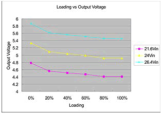
- When choosing small power products, please check the actual changing ratio of input voltage and output loading, most small power products like V1, V3, VA, VE series are unregulated, the output voltage changes upon input voltage and output loading. If the input voltage changes over 10%, choosing wide input products like VB, VBW, RBW series is recommended. If it’s only the load changing, simply choose the M1 series with semi regulated output or V4, M4, V5, VF series can overcome the issue from load changing.
- Regulated output series like V4, V5, M4, VF series use a high efficiency passive regulator at the output, upon the characteristic of passive regulator, the input no load consumption will be a consideration in those application which is battery powered base equipment.
- When choosing Pulse Frequency Modulation construction products like VB, R6, RD, RJ, RK series, the power supply should be considered to have more ratings to undertake the transient current during the start up stage. In some application this transient current maybe higher than 1A. For those power supplies with précised over load protection or limited output current, such high current may disturb the power rise up.
- When choosing Pulse Width Modulation (PWM) construction series (most wide range products of Motien like V6,V7,V8,V9,VD,VG,VJ,VK,VM,VN…), under the consideration of over load protection, a maximum capacitive load is provided and limited. An application with over capacitive load caused the trouble of start up.
- For products specified “short circuit protection”, a short at the output is acceptable. However, to provide a protection during the abnormal operation, a fuse is thus recommended to be settled at the input of the converter. This is to avoid when the overload happens, such converters keep operating and draw a high input current and burn the converter itself and other components.
- Carefully checking the working voltage come across the input and output, if there’s additional request of insulation, please check with us for the required insulation. For medical equipments, train, nuclear power, aerial space equipments where higher grade insulation is required, it has possibility to harm human body and life directly by wrong operation and damage. Don't hesitate to consult us.
- The calculation of AC (rms) = DC /1.414 is NOT applicable when proceeding a withstanding voltage! It’s understood that we usually use root mean square to stand for an AC voltage. But when proceeding an Input/output withstanding voltage test (usually called Hipot test), it’s definitely forbidden to apply the AC value from the above formula. The actual applied voltage of AC is actually nearly double of DC è AC(rms)/0.707 = AC (peak), AC(peak) X2 = AC peak to peak, the actual amplitude of applied AC voltage should be the value of peak to peak. In most cases, without a reinforced insulation, the insulator there between input and output will be destroyed by this high voltage.
|